12 — Read Datasheets and Plan Interfaces with AI
A useful interface plan explains why each connection and initialization step belongs in the design. It also explains what remains unknown. This chapter turns the source-reading skill from Chapter 11 into such a plan. You will compare a chip document, a breakout guide, and a development-board reference; extract a small set of constraints; and correct a proposal that mixes their meanings.
Start with CP04 in a new exercise folder. You need the supplied documents, a browser or document viewer, and your editor. You do not need to own the hardware. The required project continues with synthetic input in Chapter 13. The optional physical plan developed here is documentation-based; it is not evidence that a board has been assembled, powered, or measured.
Identify the object before trusting the number
“ESP32-S3 with a BME280” names two families of technology, not a complete assembly. A chip can appear on several boards, and a board can have revisions with different supporting parts. A product photograph can resemble another variant closely enough to fool a quick visual check. Before extracting a pin or a supply value, identify which physical object the source describes.
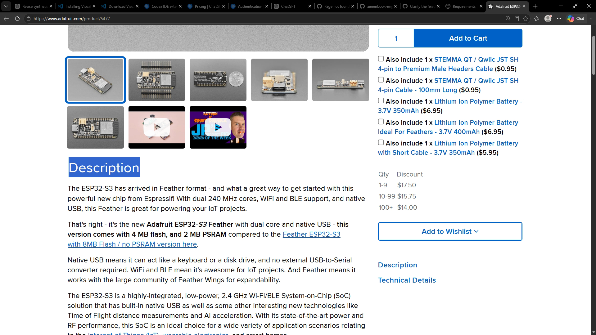
Our documented example is Adafruit product 5477: the Feather ESP32-S3 variant with 4 MB flash and 2 MB PSRAM. The product description distinguishes it from an 8 MB flash version without PSRAM. The distinction belongs in the project identity and build configuration. It is not an optional decorative detail. Adafruit product 5477.
The optional sensor is a separate Adafruit BME280 breakout. The Feather guide describes a BME280 footprint on the Feather; a footprint is a place where a component could be fitted, not proof that the sensor is present. An assistant that reads only the family description could propose reading a sensor the board does not actually contain. Check the relevant product and guide sections rather than turning a drawing label into an inventory observation. Feather pinouts, BME280 section.
Create an identity line before asking for a constraints table: “Adafruit Feather ESP32-S3, product 5477, 4 MB flash / 2 MB PSRAM; optional separate BME280 breakout; physical revision not observed.” That final clause matters. A documented example can be exact enough for source reading and compilation while its hypothetical physical instance remains unknown.
Keep chip, breakout, and host-board evidence separate
A chip datasheet answers questions about the silicon and package. A breakout guide describes additional circuitry, exposed pins, connectors, and jumpers. A host-board reference explains how a microcontroller is connected to its peripherals and external interfaces. A library or board-core source then describes what a particular software version assumes about those connections.
These sources complement one another, but their statements are not interchangeable. Bosch's BME280 technical data lists separate chip supply ranges for VDD and VDDIO. Adafruit's breakout guide describes a regulator on the breakout and a wider Vin input range. A breakout supply statement therefore cannot be copied onto the bare chip's power pin. The supporting circuitry changes the meaning of the connection. Bosch BME280 technical data, Adafruit breakout power pins.
Treat a generated table as a set of claims to inspect. For each row, ask: which object does this describe, under which conditions, and where does the source establish it? If the answer is “the source mentions something similar,” the row is not ready to drive a design decision. Move it into the unresolved list until its scope is clear.
This is a good task for an assistant because it involves organizing scattered information. The assistant can locate relevant sections, preserve units, and highlight contradictions. Your review still needs the actual section, including nearby qualifications. A polished explanation cannot make a missing board identity appear.
Read units and conditions as part of the value
Write “1000 ms,” not merely “1000.” The unit determines whether a wait is one second or more than sixteen minutes. Likewise, distinguish volts from millivolts and microamps from milliamps. A unit error can survive a compiler because both quantities may be represented by ordinary numbers.
Conditions belong beside the value. A typical current at a stated measurement rate is not a guaranteed maximum current under every configuration. An operating range is not an accuracy specification. A resolution tells you about representable increments; it does not establish that each reported increment corresponds to a correct physical measurement. Keep these meanings separate when asking an assistant to summarize a table.
For practice, use an original fictional note: “The reporting interval is 1000 ms.” An incorrect summary says “wait 1000 seconds.” The correction is not to change the firmware until its output looks reasonable. First correct the interpretation: 1000 milliseconds equals one second. Then decide whether the requirement calls for a blocking delay, a scheduled action, or merely a label on recorded data. Unit conversion and software design are different decisions.
The Sensor Monitor's one-second scheduling interval and three-second freshness limit are project requirements. They are not sensor accuracy or conversion-time claims. In Chapter 15, injected-clock tests will check the software arithmetic. A later physical driver would require its own documented timing behavior and, where appropriate, bench measurements.
Build a small constraints table
Open docs/hardware.md, docs/interface-plan.md, and dependencies.json in CP04. The first holds sourced example facts, the second states the interface approach, and the manifest holds the exact build target. Use the constraints skill explicitly if you want to inspect its procedure, or use an ordinary extraction request to test automatic selection. Record which path you actually used.
Try this bounded request:
Derive the interface constraints for the documented Feather product 5477 and optional BME280 breakout. Use the primary sources linked in docs/hardware.md. Separate chip, breakout, and host-board facts. Return claim, value and unit, source section, confidence or missing data, and design consequence. Do not edit firmware or infer an unobserved physical revision.
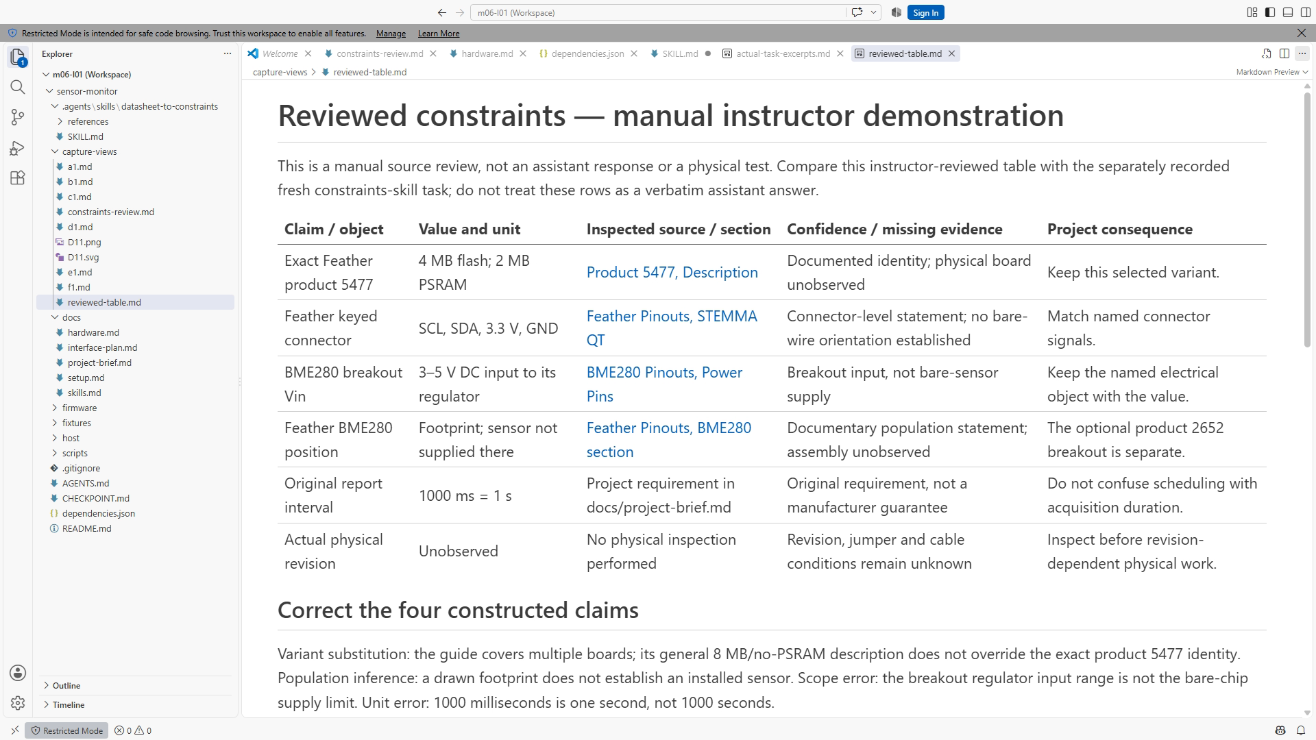
The output should be short enough to compare with the sources. The following table is a reviewed teaching example, not a transcript of an agent session:
| Claim | Value and unit | Source location | Consequence |
|---|---|---|---|
| Example memory variant | 4 MB flash; 2 MB PSRAM | Product 5477 description | Preserve the selected manifest target |
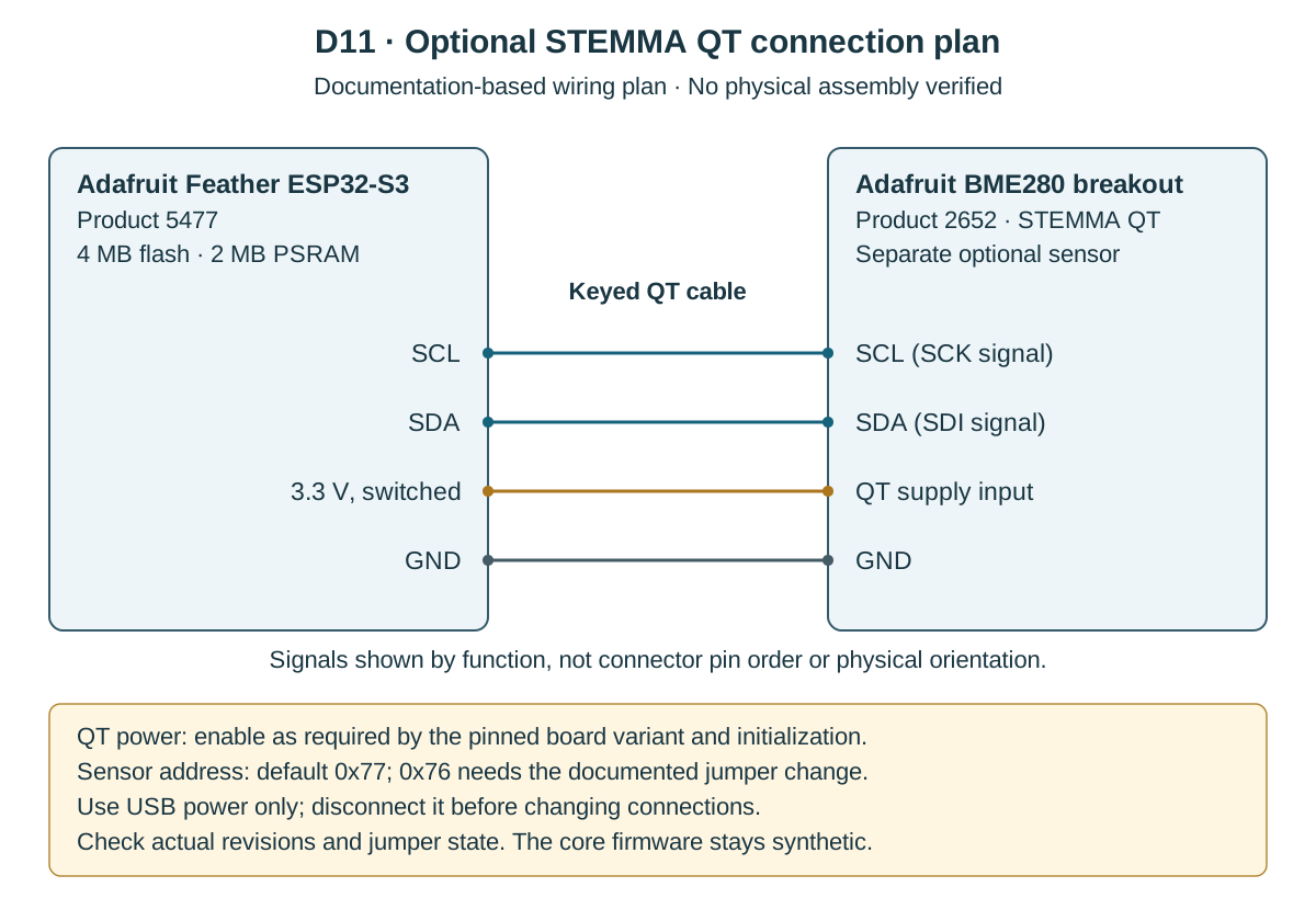
| Feather QT connector | SCL, SDA, 3.3 V, GND | Feather pinouts, STEMMA QT | Draw a connector-level interface using these signals |
| BME280 breakout I2C address | Default 0x77; alternative 0x76 with address configuration | Breakout pinouts, I2C Address | Record the intended default and leave physical jumper state unobserved |
| Physical revision | Not observed | No physical evidence supplied | Recheck the actual assembly before optional deployment |
The connector and address facts come from the applicable manufacturer guides. The last column is our design interpretation and should remain identifiable as such. The address is a hexadecimal bus identifier, not a pin number or a voltage. Feather connector reference, BME280 address reference.
Turn the table into a connection plan
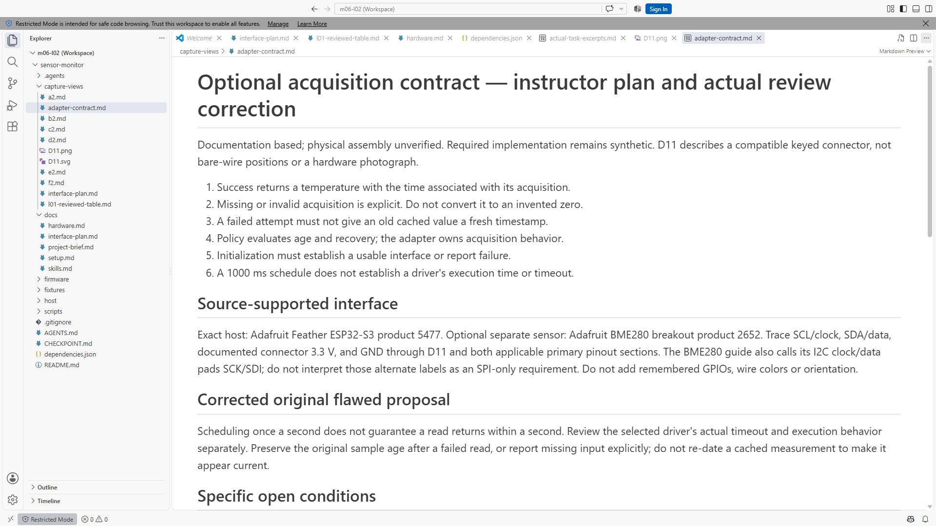
At this stage, plan the optional connection at the documented connector level: host SCL to sensor clock, host SDA to sensor data, the documented connector supply to the corresponding supply connection, and common ground. A compatible keyed STEMMA QT cable provides that connector path. Do not substitute a remembered sequence of bare GPIO numbers for the named signals.
Draw the host and breakout as separate boxes. Put the exact product identities above them and label the plan “documentation-based; physical assembly unverified.” Show four named connections and cite the sources beside the diagram. Leave wire colors out unless your actual reviewed cable documentation establishes them. A color chosen to make a figure attractive is not a connection specification.
For a bare-wire variation, the plan would need additional evidence: the exact exposed connector or header pin positions, orientation, supply assumptions, and any relevant level conversion. Do not silently expand the keyed-cable example into a generic wiring tutorial. The core task is complete when the documented interface is coherent and its limits are explicit.
Check a diagram by tracing one signal at a time against the source. Verify both endpoints, then the supply and return path. If a schematic label is too small to read, enlarge the actual source or use its text/pinout companion. Asking an image model to guess the tiny label does not resolve the ambiguity. The correct result can be a marked unknown and a request for a readable source.
Plan initialization without inventing a driver
A physical sensor adapter would need to initialize the interface and report whether acquisition succeeded. The current core project deliberately has no BME280 driver. Its input adapter supplies synthetic temperatures and a present/missing indication, leaving policy behavior testable without a board.
The Feather guide describes switchable peripheral power and uses board-specific names for its control. The guide and a pinned board-core variant must be read together before adopting a symbol in a physical adapter. A name that exists on another Feather or an older example is not enough. Record unresolved alias or initialization details explicitly. Feather pinouts, I2C and STEMMA QT sections, ESP32 core 3.3.11 variants.
Write the future adapter contract in plain language. Initialization either establishes a usable input path or returns a failure that the application can report. Each acquisition carries a timestamp and a value or an explicit missing indication. Invalid floating-point results do not become invented temperatures. A failed attempt does not refresh the timestamp of an old cached reading.
Also ask what can block. A scheduled call every second does not prove that the called driver returns promptly. The driver and bus layer need documented timeout behavior before anyone claims a bounded physical acquisition. This question can remain open for the optional extension while the shared software policy proceeds.
LAB12 — Repair an interface proposal
Allow about forty-five minutes. Preserve CP04, then create a new exercise copy. In docs/lab12-review.md, review this deliberately flawed proposal:
Use any Feather ESP32-S3 because all memory variants use the same build settings. The BME280 is already installed on the Feather. The breakout's Vin allowance applies directly to the bare sensor chip. Use 0x76 because that address appeared in another project. The example's 1000 ms interval means the program should wait 1000 seconds. Once the host replay passes, mark the wiring and sensor accuracy verified.
First mark each claim as supported, contradicted, or not established by the supplied material. Do not begin by rewriting the whole paragraph. Your goal is to identify which evidence resolves each problem. Open the product description, the board guide, and the breakout guide. Record the relevant section beside each hardware judgment. Use the original interval statement for the unit conversion.
Next write a corrected proposal of no more than two paragraphs. Keep only facts needed for the planned interface. Specify the exact example variant, separate breakout, documented connector-level path, intended default address, and unresolved physical revision. State that the core implementation uses synthetic input and that optional driver, wiring, and measurement checks remain separate.
Finally produce the small connection plan and a list of initialization questions. For each unresolved question, name the evidence that would resolve it. “Check hardware” is too vague; “inspect the actual address jumper before configuring a non-default address” names a concrete action. No physical operation is required to complete the lab.
If an assistant produces a broad rewrite with guessed pins, preserve that response as the failed attempt. Give it the exact missing-data rule and rerun the same bounded task. Compare the corrected output with the source, not merely with the previous answer. A shorter answer with one honest unknown can be the successful result.
Worked answer and review
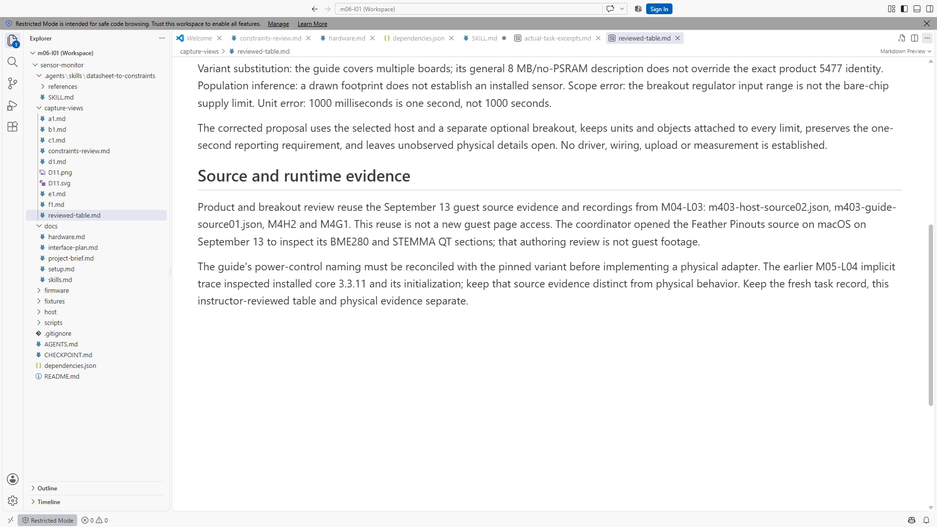
The proposal fails on identity, source scope, address evidence, units, and validation claims. The selected memory variant must match the recorded build. A footprint does not prove sensor population. Breakout input circuitry does not change the bare chip's limits. A different project's address does not establish this breakout's configuration. One thousand milliseconds equals one second. Host execution establishes none of the proposed physical claims.
A suitable corrected plan names product 5477 and the separate breakout, uses the documented QT interface, and treats the default address as a documentary assumption to check against an actual assembly later. It retains the exact target manifest and separates synthetic policy work from the future physical adapter. It does not invent a PCB revision, pin alias, or calibration result.
Your table passes when a reviewer can follow each factual row to its source and understand its consequence. Your diagram passes when each connection has a documented identity and the unverified physical status is visible. The wording need not match this answer. Unsupported certainty, even if expressed neatly, is a failed result.
Questions to check your understanding
Why can two supply statements both be correct while describing different limits? One may describe a bare chip and the other a breakout with supporting circuitry. Their scopes and connection points differ. Identify those objects before using either value.
What does an access date establish? It records when a source was checked. It does not establish the manufacture date or revision of an unseen board. Use a document revision or pinned source version where available and keep physical identity separate.
Why preserve an unknown in a nearly complete table? It shows which decision lacks support and what evidence is needed next. Filling the cell from memory hides that dependency and makes review less reliable.
Can a successful host replay validate a wiring diagram? No. It executes shared software against synthetic input. A wiring plan is reviewed against documentary evidence; an actual connection requires physical observation and suitable checks.
Transfer to your own project
Before reusing the plan, perform a small consistency review. Read the exact product identity in the README, the memory options in the dependency manifest, and the object names in the constraints table. They should describe the same example. A correct table attached to the wrong project is still misleading context. If a future board change makes one of those files obsolete, update the linked decision rather than adding a second unexplained “correct” value.
Keep a distinction between a missing source and a source you have not checked. “Not present in the supplied excerpt” calls for a fuller document; “not checked” calls for an inspection; “conflicting sections” calls for reconciliation. These labels help the next engineer choose an action. They also make a better assistant prompt than a general instruction to be more certain. Certainty is not the missing input; applicable evidence is.
Choose one interface from an existing project. Identify its chip, carrier board, host board, and software package as separate objects. Extract only five facts that affect the next decision. Include one condition or unit that could be lost in a summary and one unknown that a source cannot resolve. Then ask an assistant for the same table and compare it with your own work.
Keep the reviewed table beside the decision it supports. Update it when the board or library changes rather than copying it into several unrelated files. In Chapter 13 you will use this disciplined context to make a small software change whose behavior can be executed and inspected.
<!-- Production figures: SS12-01 exact-source identity; SS12-02 reviewed constraints; SS12-03 proposal correction; SS12-04 interface plan. D11 is the documentation-based connector diagram. Full guest captures and vector artwork pending coordinator; HP01–03 optional and unperformed. No screenshot placeholder is evidence. -->