M06-L02 — Plan the interface from documentation
Turn the reviewed constraints into a connector-level plan and a software input contract. Start from your CP04 table. The plan describes an optional physical extension; the core project will continue with synthetic samples. No wiring or upload is required.
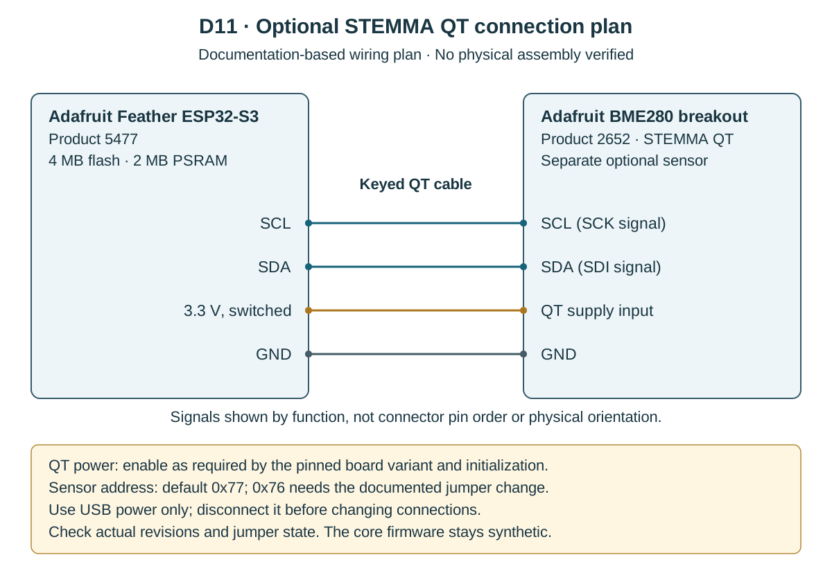
Draw the exact host board and separate breakout as two named boxes. The Feather guide identifies the QT connector's clock, data, supply, and ground signals. Use those named connections and the applicable breakout guide to trace corresponding endpoints. Do not replace them with remembered GPIO numbers or unsupported cable colors. Feather STEMMA QT reference, BME280 I2C reference.
Label the diagram “documentation-based; physical assembly unverified.” Include the exact example identity, source sections, and the fact that a compatible keyed cable is the intended connection path. If you change to bare wires or another board, the source evidence must expand to cover pin position, orientation, supply, and relevant interface conditions. That is a new plan, not an assumed equivalent picture.
Check one connection at a time against the primary material. Follow clock from host to sensor, then data, then supply and return. If a schematic label is unreadable, enlarge the actual source or locate its text/pinout companion. An AI interpretation of a tiny label cannot substitute for a readable reference. Retain an unresolved item if the exact endpoint is not established.
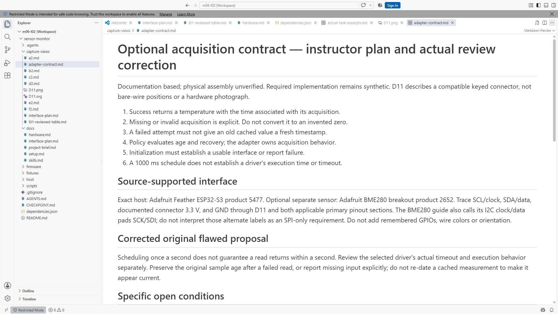
Next separate acquisition from policy. The future adapter should report a timestamped temperature or an explicit missing input. It should not invent a normal value after a failed read or refresh the age of a cached value. The shared policy decides whether input is current and whether recovery is complete. This contract allows the synthetic adapter and host replay to exercise the same policy later.
Initialization belongs in the plan too. The board guide describes switchable peripheral power; the pinned board-core variant must resolve the actual software symbol and initialization behavior before a physical driver is adopted. Record the unanswered question rather than using an alias from a different example. Feather I2C/power sections, ESP32 core 3.3.11 variants.
Ask what happens when initialization fails and what bounds an acquisition call. Scheduling work once a second does not establish a driver timeout. A physical adapter needs a selected library/version and evidence about its blocking behavior. These remain optional-extension questions; they do not prevent the required synthetic project from progressing.
The assistant's useful output is a small plan with supported connections, a clear adapter contract, and specific unresolved checks. An unnecessary sensor driver or purchase list expands the task. Review a generated plan against the constraints table and confirm it has not silently changed the board variant, address assumption, or meaning of a timestamp.
Resources and completion
Use Chapter 12, CP04 docs/interface-plan.md, docs/hardware.md, and the dependency manifest. Figure references are SS12-03, SS12-04, and D11. Complete the exercise; inspect the key (supplied separately) afterward. Optional photographs HP01–03 are not evidence available in this core activity.
Recording transcript
The constraints table tells us which facts the documents support. Now we will turn those facts into a small interface plan and a software acquisition contract. Stay in checkpoint four and keep your reviewed table open. This is a documentation exercise for an optional physical extension. The required project will still use synthetic input, so no wiring or upload is needed to complete the lesson.
Start the drawing with two separate boxes. Name the exact host board above one and the separate sensor breakout above the other. Do not replace those identities with a broad family name after doing the work to establish them. The drawing should describe the same example as the README, hardware reference, and dependency manifest. A correct connection attached to the wrong variant is still misleading context.
Use the named connector signals from the applicable references. At this level, we need clock, data, the documented connector supply, and ground. Trace the corresponding endpoint on the breakout. The intended connection uses a compatible keyed cable. Do not insert remembered GPIO numbers, unsupported wire colors, or assumptions from a photograph of a similar board. Every added detail becomes another factual claim to review.
Place a clear label on the plan: documentation based, physical assembly unverified. This is not a decorative disclaimer. It tells the next person what kind of evidence the drawing represents. The source can support an intended connection, while actual orientation, cable condition, board revision, and physical operation remain unobserved. A diagram does not become a bench result because it is carefully drawn.
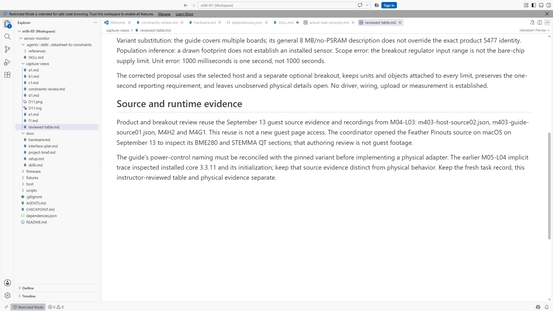
Check one connection at a time. Follow clock from the host endpoint to the sensor endpoint, then do the same for data. Check the supply connection and return path separately. Keep the source section beside each check so a reviewer can repeat it. Reading all four lines as a group makes it easier to miss a swapped endpoint or an assumption copied from another interface.
When a schematic label is too small to read, enlarge the actual source or locate a readable pinout companion. An assistant may help find the relevant material, but guessing the label from a blurred image does not resolve the uncertainty. If the endpoint is not established, mark it unresolved. A clearly identified gap is more useful than a confident line drawn to an invented pin.
A bare-wire variation would need more evidence than this connector-level plan. You would need exact pin positions, orientation, supply assumptions, and relevant interface conditions. Do not silently expand the keyed-cable example into that variation. A changed connection method is a changed engineering task, and the source checks should grow with it. The core course does not require you to perform that extension.
Now describe what the input adapter gives the application. It should produce a timestamped temperature when acquisition succeeds, or an explicit indication that a reading is missing or invalid. The adapter handles the acquisition environment. The policy decides whether the input is current and whether the application has recovered. Keeping that boundary clear lets host replay exercise the same policy without a physical sensor.
Write down what a timestamp means. A fresh acquisition can carry the time associated with that reading. A failed attempt must not take an old cached value and give it a new timestamp. That would make stale data appear current. The value, its validity, and its age belong together. If an assistant proposes a fallback number, ask which requirement gives that invented measurement a legitimate meaning.
Initialization is part of the contract as well. A future physical adapter needs to establish a usable interface or report initialization failure. It should not proceed as though input exists when setup failed. The current synthetic implementation avoids a sensor driver entirely, which keeps the shared behavior small and testable. You can define the future boundary now without claiming the future driver has been implemented.
The board guide also describes switchable peripheral power. Before adopting a control symbol in a physical adapter, inspect the selected board variant and its pinned initialization source. An alias from another example is not automatically applicable. If the guide and code use different names, record the exact question and the evidence needed to resolve it. Do not hide that mismatch behind a generic ESP32 pin number.
Ask a separate timing question: how long can acquisition take? Calling an adapter once a second does not guarantee that its internal driver returns within one second. Scheduling controls when work is requested. Driver timeout behavior controls what happens inside the request. A physical extension needs appropriate source and implementation evidence for that behavior before you describe its acquisition as bounded.
These unanswered physical-driver questions do not prevent the required synthetic project from moving forward. The host adapter can supply controlled values and timestamps while the optional implementation remains a separate task. The important boundary is visible: software policy checks will establish behavior for supplied inputs, while electrical operation, bus behavior, and measured response timing remain outside those checks.
In the exercise, review a proposal that confuses scheduling with duration and refreshes cached data after failed reads. Correct both claims in the plan before any coding. The first needs an independent acquisition-duration or timeout check. The second needs the original sample age to remain visible or an explicit missing result. Neither problem is solved by making the output look continuously normal.
Your completed plan contains the documented connections, a short adapter contract, and specific unresolved questions. Each unknown names what evidence would resolve it. Physical revision, jumper state, pinned power initialization, selected driver version, and actual upload or serial operation are useful examples when they affect the planned extension. Avoid an indiscriminate list of every conceivable risk; keep the questions tied to this interface.
Finally compare the plan with the constraints table one more time. Confirm that no variant, address assumption, or source condition changed while the drawing became more polished. Ask the assistant for a bounded review if it helps, then inspect the source evidence yourself. In the next lesson we will implement and run synthetic input handling, using this clear acquisition boundary to keep the firmware change small and its results easy to explain.
Download transcript